Photos of SUNSAT |
|
|---|---|
|
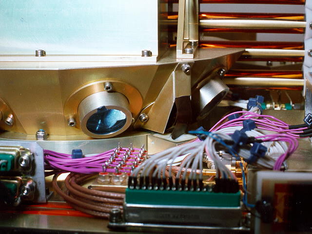
SUN01.JPG - Close-up of laser-reflectors
on facets of the tip mass.(60K) Corner cubes reflect laser beams directly back to the laser irrespective of arrival angle , enabling "cat's eye"-type reflections to be obtained from the satellite. NASA laser ranging stations can determine the range to millimetre accuracy.(5th March 1997). |
|
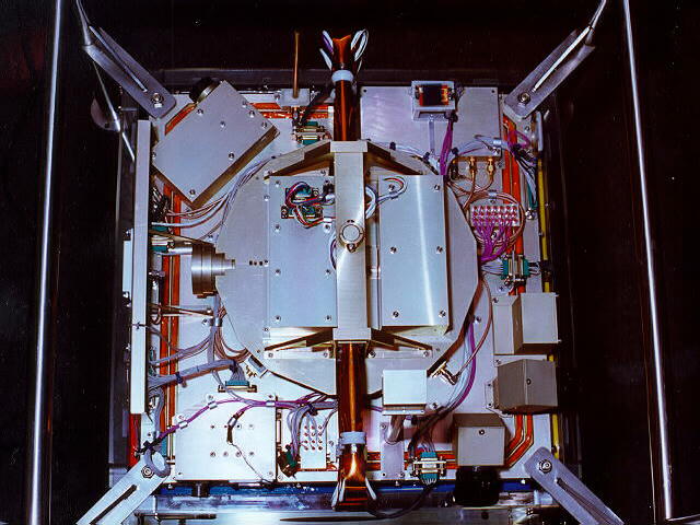
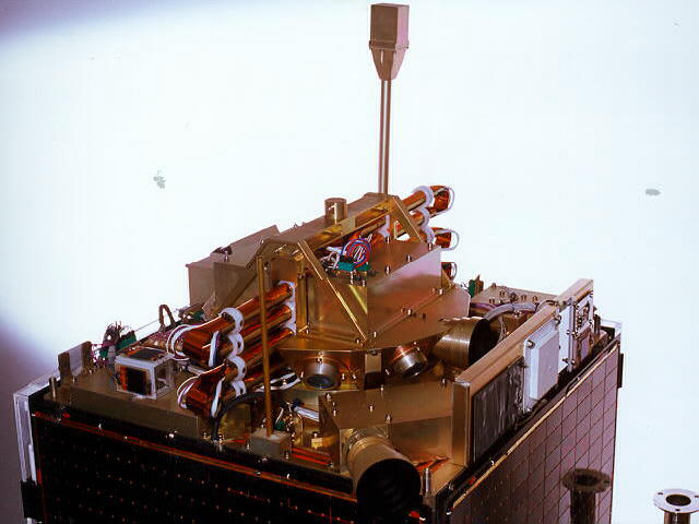
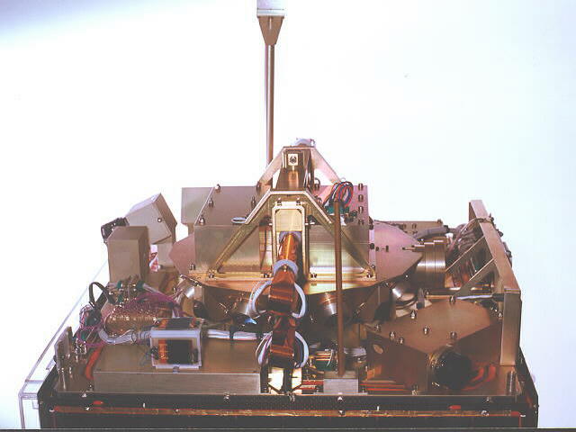
SUN02.JPG - Top view of SUNSAT in it's handling frame.(70K) Top surface of SUNSAT without solar blanket shows the octagonal tip mass with it's star camera lens (left), and other sensors.(5th March 1997). |
|
SUN05.JPG - Side view of top plate showing horizon sensors
(73K)
Horizon sensors inclined 30 degrees downwards are visible on the front right corner. Spanning 30 degrees field of view, the 2048 element linear CCD sensors measure the satellite's orientation relative to the earth in their two planes with a resolution of better than one arc-minute.(5th March 1997). |
|
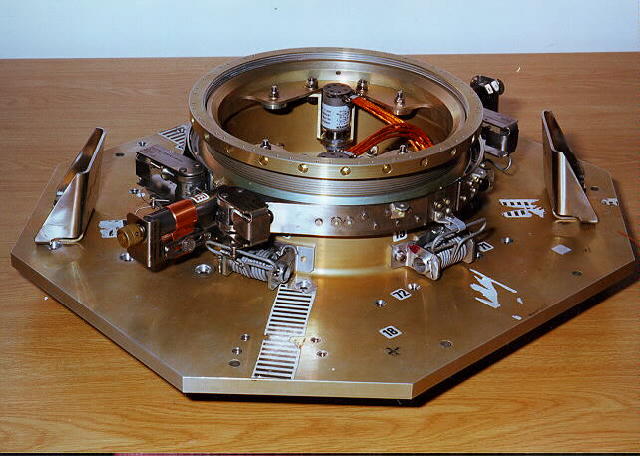
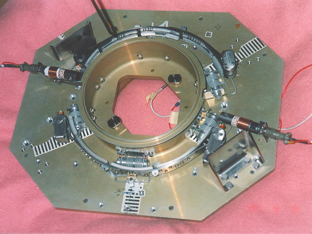
SUN06.JPG - SUNSAT's PAA and PAF
(59K) SUNSAT's Payload Adaptor Assembly (PAA) is a threaded cylinder screwing into the bottom of the satellite. The clamp-band presses V-blocks against angled flanges on the mating surfaces of the PAA and PAF during launch. Explosive cutters release the clamp-band to free the satellite. A seperation switch and the PAA locking ring are seen on the PAA. Stainless steel bumpers (left and right) protect satellite antennas from being struck by the clamp-band.(5th March 1997). |
|
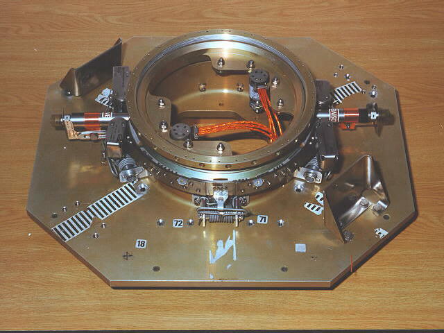
SUN20.JPG - Payload Adaptor Fitting (PAF) after satellite release.(55K) The Payload Adaptor Fitting (PAF) of the rocket is a plate with a protruding cylinder onto which the satellite is clamped. The clamp-band is shown here after being seperated by pyrotechnic bolt cutters to release the satellite.(5th March 1997). |
|
SUN17.JPG(57K) Mated PAA and PAF showing seperation switches on PAA.(5th March 1997). |
|
SUN04.JPG - Top view of star camera
and GPS antenna.(44K) Star camera is on the near corner. The white GPS Patch antenna is on the plate on the right of the photo together with the particle detectors.(5th March 1997). |

|
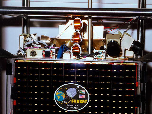
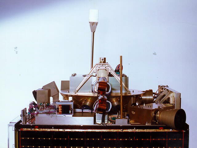
SUN15.JPG - Top plate showing folded 2.4m boom.(44K) The boom has five tubular sections joined by Beryllium-Copper springs. When the retaining bolt is pyrotechnically severed, the tipmass is released allowing the boom to straighten with the tipmass 2.4m above the satellite. This separation of the 4,5kg tip mass gravity gradient stabilises the satellite and isolates the tip mass magnetometer from spurious magnetic fields near SUNSAT.(5th March 1997). |
|
SUN16.JPG(64K) Top view of SUNSAT in handling frame.(5th March 1997). |
|
SUN18.JPG - Precision yaw sun sensor and laser reflectors.(62K) The yaw sun sensor has a vertical split in the black aperture plate which projects onto a horizontally mounted 2048 pixel linear CCD.The round laser reflectors on the tipmass are seen in the background. (5th March 1997). |
|
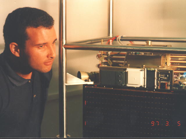
SUN19.JPG - Zaahied Mohammed of the Peninsula Technicon showing his particle impact
detectors on SUNSAT.(34K) Zaahied Mohammed of the Peninsula Technicon photographed with his own (left) and NASA-supplied particle impact detectors on either side of white GPS Patch antenna. The NASA detectors were arranged by Dr Bill Kinhard of NASA. (Thanks Bill !) (5th March 1997). |
 |
SUN03.JPG - Top plate(43K) Picture description will follow.(5th March 1997). |
|
| SUN07.JPG(61K) Complete SUNSAT on lower of handling frame.(5th March 1997). |
|
|
SUN08.JPG(64K) SUNSAT inverted on top half of handling frame with slow-bus solar panel removed.(5th March 1997). |
|
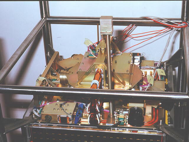
| SUN09.JPG(77K) Inverted SUNSAT in complete handling frame prior to installation of PAA/PAF. (5th March 1997). |
|
|
SUN10.JPG(68K) PAA and PAF installed on inverted SUNSAT.(5th March 1997). |
|
| SUN11.JPG(58K) Dirk vd Merwe (left) and Kobus vd Westhuizen about to install PAA onto SUNSAT. (5th March 1997). |
|
|
SUN12.JPG(65K) Cleaning threads in lower plate of SUNSAT prior to PAA being screwed into lower plate. (5th March 1997). |
|
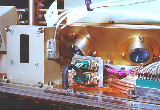
| SUN13.JPG(69K) Close-up view of slow-bus wiring harness and solar panel under perspex cover.(5th March 1997). |
|
SUN14.JPG(40K) Picture description will follow. |