PRE-FLIGHT PERFORMANCE OF SUNSAT, SOUTH AFRICA'S FIRST
REMOTE SENSING AND PACKET COMMUNICATIONS MICROSATELLITE
A. Schoonwinkel, G.W. Milne, S. Mostert , W.H. Steyn and K. van der Westhuizen
Department of Electrical and Electronic Engineering
Stellenbosch University. Private Bag X1, MATIELAND, 7602. South Africa.
Fax: +27 21 808 4981. schoonwi@firga.sun.ac.za. http://sunsat.ee.sun.ac.za
ABSTRACT
This paper describes the total system configuration, flight model components and pre-flight tests of the SUNSAT microsatellite which is to be launched in 1997. A very modular satellite mechanical structure has been constructed and environmentally tested. The first performance measurements of the payloads (a 15 m resolution imager, VHF, UHF, S and L band communications systems and space science experiments) are reported. The operation of the attitude determination and control system and other bus systems is described, indicating that a very complex microsatellite was developed as the first venture into space by a South African university. The microsatellite was built with a tight budget, sponsored largely by local private industry. The major spin-off from the programme is an established electronics systems laboratory where students can gain multidisciplinary engineering experience on a challenging project.
INTRODUCTION
SUNSAT, an advanced microsatellite developed by graduate students at Stellenbosch University in South Africa, will be launched by NASA from Vandenberg Airforce Base on a Delta II rocket in May of 1997. The Flight Model hardware is nearly complete and is now being pre-flight tested. A previous paper1 discussed the preliminary systems level design concepts as well as specifications of the various payload and bus subsystems. This paper commences with a technical overview of the overall system, which comprises of three main payloads, namely a push broom type imager, packet communications systems and scientific experiments for NASA.
Laboratory measured performance data are provided for the 15 m resolution 3 colour CCD imager of SUNSAT, developed jointly by Stellenbosch University, the Council for Scientific Industrial Research (CSIR) in South Africa and the Korean Advanced Institute of Science and Technology (KAIST). The realisation and laboratory tests of VHF and UHF amateur radio compatible communications modules are described, as well as the operation of an S-band down link transmitter for image data and an L-band up link for rapid file transfers.
The performance of the various satellite bus systems is also described. The paper is concluded with a summary of the labour, financial and research investments made during the development life cycle of SUNSAT from inception to flight model completion. The benefits and future of the microsatellite development laboratory at Stellenbosch University are also discussed. Amateur radio aspects of the project are described in other publications11.
BACKGROUND
The SUNSAT programme set out in 1992 with three major goals, namely to enrich the engineering graduate training programme at Stellenbosch University, to expand international scientific co-operation and to stimulate interest in technical careers among school children. The local development of a microsatellite with a number of novel subsystems has provided the technical challenge and excitement required to achieve these goals.
Now, 4½ years after commencing the programme, more than 50 graduate engineering students at Master's and PhD. level have contributed to the endeavour through research and development work. Several apprentice technicians have also completed their practical training in the SUNSAT laboratory.
International collaboration has provided a launch opportunity for SUNSAT in 1997. NASA has agreed to launch SUNSAT free of charge as an auxiliary payload on their P-91 Delta mission2. In exchange, the SUNSAT microsatellite has been modified to incorporate a NASA supplied GPS receiver, and a set of laser retro-reflectors. Under this agreement the SUNSAT microsatellite will supply NASA scientists with data from their instruments, which will enable them to study gravitational effects by means of orbit perturbations.
The appeal of space applications to school children is being used to involve them in the SUNSAT programme3. Inside the structure of the microsatellite, room has been reserved for several projects designed and built in school science laboratories. Projects received so far from high school pupil teams include sensors that measure temperatures in space, structural acoustic noises and the effects of radiation on electronic devices.
The SUNSAT architects deliberately decided that students should build as much of South Africa's first satellite as possible. It was also decided in 1992 that SUNSAT would not be a copy of any existing microsatellite. Attempts have been made to achieve improved technical performance in selected microsatellite subsystems, as described in the sections to follow.
TECHNICAL OVERVIEW
Mission specification
SUNSAT 1 is to serve as a technology demonstrator. The programme's originators decided to take a high risk approach by developing a fairly complex microsatellite in their first attempt. The aim is to test as many subsystems as possible in a 60 kg, 45 x 45 x 60 cm satellite, which has an average power availability of approximately 30 W from body mounted solar panels.
Figure 1 shows an engineering drawing of SUNSAT 1 in the operational configuration with its gravity gradient boom deployed. Figure 2 depicts the satellite prior to release from the launch vehicle.
The SUNSAT microsatellite will carry remote sensing, communications and scientific payloads that will be described later in this paper.
The orbit was chosen to suit the Danish Ørsted satellite, whose primary mission is to map the earth's magnetic field. Due to an inclination of 97° the orbit drifts at approximately one hour in 70 days relative to the earth-sun vector. The altitude varies between 450 km and 860 km. Even though this orbit is not ideal for SUNSAT's remote sensing payload, is was accepted because it triggered close interaction with NASA researchers and permits SUNSAT's design in a sunsynchronous orbit to be evaluated.
The Mission to Planet Earth scientific payloads are the NASA provided GPS receiver and laser retroreflector. A scientific magnetometer is provided by the Hermanus Magnetic Observatory (South Africa). This sensor is co-located with a star camera on the tip of SUNSAT's gravity gradient boom to provide the magnetic field vector. This data will be analysed in conjunction with magnetic data from the Danish Ørsted satellite which is to be launched in a twin orbit with SUNSAT.
The design life time for SUNSAT is 4 to 5 years, with the number of recharge cycles of the NiCd batteries expected to be the limiting factor.
Overall system design
SUNSAT follows many of the concepts of the University of Surrey's UoSAT series4, but with a few distinct differences. The major research contribution is upgrading the imaging performance and incorporating a high accuracy attitude control system.
The camera system on SUNSAT is designed to provide stereo or side view images in three colours. Each colour has 3456 pixels per line with 15 m ground resolution from 800 km orbit height. This resolution is of the same order of magnitude as the SPOT and Landsat satellites. The quality and variety of SUNSAT images will be unique for a university microsatellite.
The communications payloads comprise high speed data links and as well as Amateur Radio transmitters and receivers in the 145 and 435 MHz amateur radio bands. A separate S-band downlink will convey image data at up to 60 Mbit/s to the 4.5 m diameter dish antenna at Stellenbosch and possibly at other locations. An L-band receiver on SUNSAT permits uplinking of data at 2 Mbit/s, and can be coupled to the image data transmitter for data gateway experiments. This means that large data files can be exchanged among remote locations on earth which are not well served by other Amateur communications systems.
The satellite orientation and control system uses reaction wheels and magnetorquers to point the satellite camera's boresight to within 1 km accuracy on the ground. This accurate position control system on SUNSAT for fine pointing of payloads is a novel addition to this class of gravity stabilised microsatellites.
SUBSYSTEMS DESCRIPTION
The usual bus systems exist such as the power system, on-board flight computers, telemetry and telecommand systems. More details on the performance of these Flight Model subsystems are given in the sections that follow. Figure 3 shows a Functional Block Diagram of the subsystems of the microsatellite itself.
STRUCTURE AND LAY OUT
Modular Configuration
The need to accommodate a variety of payloads within a standard microsatellite launcher envelope, coupled with increased demands on packing density, economy of manufacture and ease of fabrication, led to the selection of a modular design for the micro satellite platform. This configuration is similar to the later satellites produced by the University of Surrey with its UoSAT program.
SUNSAT is constructed like a sandwich with a base plate and a top plate, and trays in between. The stacked trays form the central structure onto which solar arrays are mounted as seen in Figure 4. The advantages of a tray structure are the optimal use of the available volume and ease of fabrication, especially for the electronic hardware, and modularity of the design. A larger number of individual structural components were therefore used to simplify manufacturing. This has the additional advantage of providing many interfaces that promote damping of vibrations during launch.
Each tray, as well as the top and base plates, have holes on their corners through which a tie rod passes. Nuts on the threaded ends of the tie rods are torqued to press the satellite body together.
Each of the 11 trays houses particular electronic and mechanical components. A typical tray forms one subassembly and consists of 4 sides, 2 support beams and a printed circuit (PC) board. Although a complete tray could be machined from a solid block to avoid problems in joining processes and to follow the minimum component count philosophy, the decision was made in SUNSAT to machine the four sides separately. This reduced manufacturing costs and improved functional flexibility. This flexibility proved to be a significant advantage when the additional GPS (Global Positioning System) electronics had to be accommodated at a late stage in design.
The structural configuration of SUNSAT also provides easy adaptability for future missions.
Structural Design
Requirements of the imager aperture and launch vehicle interface meant that the base plate, payload launcher adapter, trays and top plate for SUNSAT had to be designed from scratch.
The design of the main satellite structure, satellite components and support equipment are dominated by functional requirements, mission requirements, financial constraints, and, in particular, launch requirements for the complete satellite. Extensive finite element modelling was used in the optimisation and analysis of the satellite structure and some of the satellite components. Various tests were performed to confirm compliance with the design requirements.
The primary design requirements for the structure are that the cantilevered modes' lowest natural frequency for the complete satellite (when mounted rigidly on the payload adapter assembly) must exceed 70 Hz, and that launch accelerations must be survived. A finite element model of the payload adapter, base plate and lowest tray, with the remainder of the satellite represented by a concentrated mass, was used to optimise the rib configuration in the base plate.
Modal survey
Characteristic structural vibration frequencies, mode shapes, and modal damping for SUNSAT were identified in order to fulfil the modal survey test objectives and as required by NASA and McDonnell Douglas Aerospace (MDA). In a subsequent finite element analysis of the complete satellite structure, the first two lateral bending modes were found to be 69.0 and 70.5 Hz. The target modes (modes below 100 Hz), as calculated with the satellite finite element (FE) model, were all identified and measured from the test data. Modal survey tests gave corresponding measured frequencies of 64.6 and 67.4 Hz. The test data met the required orthogonality requirement and had good coherence. The frequency comparison between the test modes and analytical modes shows that the pre-test FE model already represents the actual test hardware dynamic behaviour fairly well, even without any FE model adjustments.
The originally defined target modes, and those measured and identified during the modal test, were all correlated to the calculated modes of the pre-test FE model until the prescribed frequency and cross-orthogonality requirements were met. After correlation the first two lateral bending modes were calculated as 65.5 and 66.7 Hz. The dynamic behaviour of the adjusted pre-test FE model therefore closely represents the test article dynamic behaviour.
The same adjustments were implemented on the dynamic FE model so that the dynamic model can represent the final flight hardware as closely as possible.
Structural Material
Aluminium alloy 7075-T6 was selected for all of the primary structural parts and most of the component structures. It has a good strength- and stiffness-to-weight ratio, can sustain the expected temperatures, and has a high thermal conductivity to reduce thermal shock stresses. It has moderate corrosion resistance, is non-magnetic, is readily available at reasonable costs and is easy to machine. It is also not susceptible to cold welding when in contact in vacuum. A number of surface-coating processes are available to allow tailoring of surface characteristics for hardness, thermal emission, thermal absorption, corrosion, etc.
The aluminium structure, consisting of top plate, trays, base plate and payload adapter assembly, have a mass of approximately 15 kg. This is 25% of the satellite's total mass.
Strength Analysis and Vibration Testing
Analysis and testing procedures, at launch accelerations, were performed for strength design verification of both the main satellite structure and some of the satellite components.
The Delta launch vehicle static and dynamic loads (excluding shock loads and random vibration) were included in the limit load factors (maximum accelerations of satellite centre of gravity) provided by McDonnell Douglas Aerospace. These steady loads were used for strength analysis of the primary and secondary satellite structure. The finite element model used for the modal analysis was also used for the stress analysis of the primary and secondary structural elements. The limit load factors were multiplied by a 'no test' factor of 2.0 as no static load tests are planned for the primary satellite structure. The minimum computed safety margin exceeds the value of 0.65 of the yield strength, as required by MDA.
The integrated satellite will also be vibration tested on an electrodynamic shaker to protoflight vibration levels (flight levels plus 3 dB). These vibration values (random and sinusoidal) are based on actual in-flight measurements as provided for the Delta launch vehicle.
Gravity Gradient Boom and Tip Mass
A low cost gravity gradient boom (see Figures 1 and 2) was designed consisting of 400 mm pipe sections with flexible tempered beryllium copper alloy (C17200) hinges in-between. Each hinge basically consists of two 'measuring tape' - profile sections clamped face to face to the two sides of the 15 mm diameter pipe sections. The boom is folded up in sections and clamped between the two structural halves of the boom tip mass. Specially designed spacers and locators secure the boom in place during launch vibration loads.
The hinges maintain some stored elastic energy in their folded position which acts as a straightening moment during the deployment of the boom after tip mass separation. The tip mass is clamped to a support ring with one bolt during launch. The bolt is fixed to the support ring and is torqued by a nut on top of the tip mass. The height of the gap between the two tip mass halves is such that it slightly bends the GG boom pipe sections through in the middle during separation bolt preload. The load compresses the boom spacers, which prevents rattling of the boom under vibration loads. The bolt is cut by a pyrotechnic cutter to deploy the boom after satellite placement in orbit. A second cutter can also be fired if the first one fails to cut the bolt. The compression of the boom sections also acts as a leaf spring to aid initial deployment of the tip mass.
The decision to design and manufacture a gravity gradient boom in-house was done due to the high cost of alternative boom mechanisms available elsewhere. The shorter and thinner boom has less aerodynamic drag during the low (higher atmospheric density) part of the orbit and will not place an uncontrollable disturbance torque on the satellite. The shorter length also places the CG and centre of pressure points of the satellite closer to each other.
The 4.2 kg tip mass is designed to mount 8 laser retro-reflectors on 8 equally spaced facets and a star sensor and magnetometer with supporting electronics on the inside. The mass of the tip mass is determined by the requirements of the attitude determination and control system.
The integrity of the gravity gradient boom and tip mass design was verified during a sinusoidal and random vibration tests. Many tests, with the satellite, boom and tip mass suspended in a simulated zero gravity position, were performed to verify correct deployment of the boom.
IMAGER PAYLOAD
One of the main research goals of SUNSAT is to maximise the imaging capability of low cost microsatellites. This has to be achieved while constrained by cost and by launcher interfaces, and by a desire to retain a modular tray construction in the satellite. The goals and consequent compromises led to a three-colour pushbroom imager concept using three Texas Instruments TC104 linear CCD sensors. These sensors have 3456 linearly arranged pixels with 10.7 micron spacing, and maintain a good MTF (modulation transfer function or spatial frequency response) over the visible and near infra-red band.
The imager is located in the bottom tray of the satellite, and comprises a single 12 cm diameter optical tube assembly containing a 45 degree mirror, lens system, pentaprism with dichroic colour splitter, three vertically mounted linear CCD's, and their clock drivers and output buffers. The optical tube is mounted diagonally across the bottom of the satellite on bearings, and can be rotated by a stepper motor as shown in Figure 5.
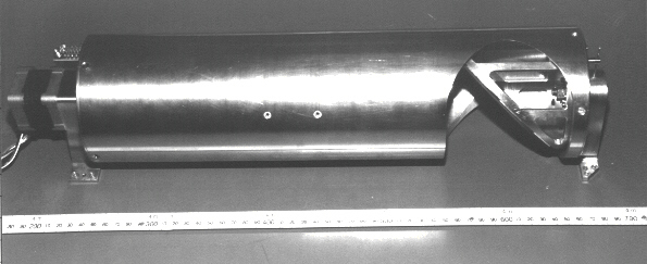
Stereo images are taken with the optical tube horizontal and normal to the velocity vector. The CCD pixels then form a line on the ground that is normal to the velocity vector, and is able to be pitched forward or backwards by up to 22 degrees to obtain various stereo base/height ratios. By orbiting with the tube parallel to the velocity vector, images to the left or right of the ground track can also be taken.
The optical trade-offs described in the previous AIAA/USU paper1 led to a choice of a 560 mm focal length, 10 cm diameter reflective optical system. The diffraction-limited resolution that was predicted in that paper for a wavelength of 0.7 microns was 32%. Subsequent design work including the effect of baffles and manufacturing tolerances has reduced the expectation to 25% for the optics alone. Laboratory tests of the pre-flight imager have produced MTF figures of 18% for the combined optics and CCD sensors.
The quantum efficiency and MTF of the TC104 are good from 0.4 to 0.9 micron. This enables the spectrum to be split into three sub-bands, with the 10% to 90% transition occurring over 20 nm optical frequency range. The 50% transition points are set at 0.52, 0.61, 0.70 microns and 0.75 to 0.9 microns which are close to the LANDSAT 6 bands 2, 3 & 4 of 0.52--0.60, 0.62--0.69, 0.76--0.90 micron.
Signal to noise, electronic gain and quantization
The TC104 is capable of a 1000:1 dynamic range (saturation signal/p-p noise). The integrated energy on a pixel falls with the third power of pixel size, so SUNSAT's small pixel produces only 20% of the CCD's saturated signal level for a 30% reflective object and normal solar incidence. The signal to noise ratio is 210:1 which is adequate for the eight bit quantization which follows a four-step switchable electronic gain. Experiments have shows that a one-bit noise can be achieved.
Special features of the optics
Maintaining stable focus and alignment on the optical system is a challenge, and has led to a design using fused quartz for the optical elements and the lens barrels. The CCD's are bonded to a quartz pentaprism which separates the three spectral bands onto their respective sensors. Special alignment techniques are used to obtain simultaneous alignment and focus on all the CCD's. The imager has a fixed focus at infinity which means that resolution tests require a collimator which can have a degrading effect on measured image resolution.
On-board digital image handling
The 64 Mbyte RAM enables a three-colour square image to be stored for later downlinking. A FPGA based data compressor can be activated for real-time image compression. Only 3456 of the 3490 pixels are active in each image line. Eight of the unused bytes of digitised information can be filled with data from the flight computers. The bytes will be filled with frame synch words, time, orbital, and attitude information to ease configuration management of archived image information.
Further details of experimental work are in a paper specifically on the imager performance8.
Overall, the complexity of developing space quality optics was far more difficult than anticipated. The major hurdles that had to be overcome were aligning the 3 CCD's on the exact same optical path and compensating for the differential thermal expansions between the CCD elements and the optical components.
COMMUNICATIONS PAYLOAD
Table 1 : Imager Specification Summary
Linear CCD Sensors                          Three x TC104

Filters, 50% transmission                   0.52 -- 0.61 micron

                                            0.61 -- 0.70 micron

                                            0.76 -- 0.87 micron

Sensor pixel size                           10.7 micron

Number of pixels                            3456 active pixels, 3490 total
                                            per band

Lens focal length                           560 mm

Aperture diameter                           100 mm

F number                                    1:5.6

Earth pixel size at 850 / 450 km            16.24 / 8.6 m

Image width from 850 / 450 km               56.125  / 29.68 km

Max. stereo strip length from 850 / 450 km  Approximately  850 / 450 km

Line scan rate at 850 km / 450 km           397.68 / 841.78 lines/sec

Quantization                                8 bit

Electronic gain                             0 dB, +3, +6, +9 dB

Bit rate/channel. Square pixels at 850 km   11.1 / 23.5 Mbit/s
/ 450 km

Three-band bit rate. Square pixels at 850   33.3 / 70.5 Mbit/s
km / 450 km

CCD output 100% reflectivity                70% of saturation

Saturated signal / p-p noise                1000:1

30% reflectivity signal / p-p noise         210:1
SUNSAT's communications provide for amateur radio communications (VHF, UHF, L, S bands), data downlinking (VHF, UHF, S-Band), data collection (VHF, UHF), and command and control. Different frequencies are at times required for the different services, but allocations of nearby frequencies will permit use of common satellite equipment. Final frequency allocations are still in process in South Africa, so are not available at present. The design can handle uplinks from 144-150, 400-403, 435-438, 1265 MHz, and downlinks at 136-138, 143-146, 400-403, 427-430, 435-438, 2250 MHz. Synthesisers, and easily changed crystals make a late change to specific frequencies feasible. Previous papers1 described the basic communications system on SUNSAT. This section will add further information, particularly on the antenna system.
Figure 1 shows the underside of the satellite which contains an S-band helix, L-band monopole, VHF monopole and canted UHF turnstile. The deployed VHF turnstile can be seen on the top of the satellite, and in its folded and retained position under the tip mass in figure 2, which also shows the UHF monopole.
The proliferation of antennas is to provide redundancy. Figure 6 shows a block diagram of the UHF communications system. All RF modules are located in the UHF tray. The VHF system is very similar, so will be described simultaneously.
Figure 6 : UHF Communications System Block Diagram
The receiving system design provides for full redundancy. The hybrid of the turnstile antenna splits the transmitter and receiver paths. The received signal passes through the VHF trap into the UHF preamplifier and into receiver RX4. This has two crystal frequencies and a synthesiser feed. The monopole is also trapped and fed into the top preamplifier channel and into receiver RX3. Either antenna, preamplifier, or receiver can fail and communications will still be maintained, albeit with less desirable antenna patterns. By toggling the preamplifier relay, the receivers can also be swapped between preamplifiers for further flexibility. The VHF system has a similar layout, but replaces each UHF preamplifier with a pair of pin-switchable preamplifiers. The extra redundancy is provided since the VHF receivers are the prime uplink receivers for amateur use.
The transmitters have duplicated exciters labelled as TX3 and TX4. The exciters are passively combined with the UHF QPSK exciter output and fed to both power amplifiers, PA3 and PA2. PA2 will normally be the operating transmitter. The UHF relay can switch the turnstile to PA3 if PA2 fails. The additional relay enables the two PA's to transmit via the monopole if the cable to the hybrid fails.
The I and Q channels of the QPSK modulator are fed by a DSP output, enabling complex modulations to be generated via software. SUNSAT will thus be able to test complex modulation schemes in future research programs. The VHF system has no QPSK modulator, but instead has a receiver 455 kHz IF output that feeds the DSP system to enable new DSP demodulators to be evaluated. The other VHF receiver has four FM demodulators to provide many uplink channels to the satellite. The four channels will reduce receiver blocking when amateurs beyond terrestrial link range simultaneously attempt to access the satellite.
All receivers have been optimised for sensitivity with 15 kHz IF bandwidth. A few dB's are lost due to traps, protective diodes, combiners and cables. Spurious responses have also been controlled, so that at all frequencies except the desired frequency and main image frequency, received signals of -50 dBm will not influence reception9. The system has been designed for full duplex reception at VHF and transmission at UHF. The reverse operation far away from the third harmonic may also be possible, but needs further testing.
The power amplifiers have 5W output at VHF and S-band and 10W output at UHF, and can be commanded into a lower power mode to reduce power consumption.
The S-band downlink will permit QPSK transmission of the data described in the imager section. The transmitter can also be fed from a PAL TV camera on the satellite, which will be used for school interest, and possibly for visual orienting of the satellite during commissioning. The L-band uplink is capable of 2 Mbit/s data uploads for upgrading software. In addition, it can be linked to the S-band power amplifier to act as an amateur transponder into the 2400-2450 MHz amateur/ISM band. The received signal levels will be small, and possibly interfered with by the 2400 MHz wireless LAN operations, depending on location10.
ATTITUDE DETERMINATION & CONTROL SYSTEM
SUNSAT will be an earth pointing satellite (body Z-axis towards nadir) to keep the imager in a nominal direction for usage and to provide acceptable antenna gain. The gravity gradient boom and tip mass will stabilise the satellite nominally earth pointing, thus requiring minimum control energy. The satellite will be kept in a slow Z-spin during normal operation (not during imaging), for improved solar thermal distribution. The four solar panels on the X/Y facets will thereby receive an even solar illumination, resulting in an improved life span of the solar cells and better thermal distribution on the satellite. A simple momentum transfer to a Z-axis reaction wheel will despin the satellite before imaging sessions.
The following attitude control hardware is utilised: 3-Axis reaction wheels to provide an accurate, continuous and fast control capability. The maximum wheel angular momentum is 0.25 Nms per wheel. 3-Axis magnetic torquer coils are also employed to ensure high reliability and long life actuation. Magnetic torquing is used as the primary active stabilisation method to do libration damping, Z-spin rate control and momentum dumping of the reaction wheels.
The following attitude sensing hardware is utilised: 3-Axis fluxgate magnetometer is used to measure the strength and direction of the geomagnetic field vector. This information is used to calculate the magnetic torques and to obtain full attitude information by comparing the measurements to geomagnetic field model data. 2-Axis horizon sensor utilising a linear CCD array to obtain mainly pitch and roll attitude angles within a 15 range to an accuracy of 0.02. A fine slit sun sensor of similar CCD technology to obtain mainly yaw attitude information within a 60 range to an accuracy of below 0.1. A star sensor where a 10×10 image is projected onto a 752×582 interline transfer CCD. The dynamic range of the star sensor is limited to the range Mv 2.5 and Mv 6.5 to measure the angular position of a star to an accuracy (1) of at least 12 arcsec. A minimum of 3 separated stars must be detectable within the sensor's field of view to employ a full attitude determination algorithm using a star catalogue.
Due to the high processing load required by the multi-mode attitude determination and control software a T805 (transputer) microprocessor is dedicated to this task. To keep the system redundant, most ADCS functions can also be implemented on one of the onboard computers, whenever the dedicated processor might fail. Under normal conditions low level interfacing to the sensors and actuators will be done by a 80C31 microcontroller.
The reaction wheels on SUNSAT are only used during imaging sessions of the main payload. Pointing and tracking controllers are used to obtain accurate and low distortion images. To enable fast pointing to a selected target, a near minimum time eigenaxis rotation algorithm is employed. Figures 7 and 8 show a typical imaging session: The satellite is first rotated in near minimum time to an attitude of 20 roll, 30 pitch and 45 yaw. It is then 3-axis stabilised in this attitude for the total imaging period of the push broom camera and then rotated back to its nadir pointing attitude. The residual angular momentum which accumulated on the reaction wheels during imaging (mainly caused by the cancellation of gravity gradient and aerodynamic disturbance torques by the wheel controllers) is finally dumped by utilising the magnetic torquers. Only the switching polarity of the magnetic coils is shown in Figure 7.
FLIGHT COMPUTERS
This section describes the on-board computer system from a user point of view. It then describes the hardware architecture and gives an overview of the on-board software.
Functionality required
From the mission requirements the following functions are assigned to the on-board computer system:
Hardware Architecture
The satellite consists of two general purpose on-board computers (OBCs) and a dedicated attitude determination and control processor (ADCS). The two onboard computers are an Intel 188EC and Intel 386EX. The ADCS processor is a T800 transputer. In addition, there are numerous support processors (mostly 80C31 micro controllers) with dedicated functions.
The on-board computers, memory and hardware for the payloads and bus are interconnected by the following communication channels on the satellite:
The fault-tolerant design philosophy adopted for the satellite dictates that each communication channel between two hardware subsystems must be backed up by at least one other communication channel. Figure 9 shows the processor architecture and the information flow on SUNSAT.
Software
This section describes some aspects of the engineering process followed in creation of the SUNSAT software and is followed by a short discussion of the compiler environment. The run time architecture is described and some points of the application level software are discussed.
The on-board computers have been designed to allow for bootloader firmware which checks processor integrity and uploads the application level software on demand. This concept is currently being used extensively in the software development cycle on the satellite.
Design and specification
The space segment software structure has been designed using the mechanism described in a separate paper5. The design method is built around a number of complementary visual languages. The languages include a data flow language, state charts, visual project management status and hierarchical class diagrams (from object oriented analysis and design methods).
The top level design making use of the data flow language is shown in Figure 10. The processes are shown as rectangles, communication paths are shown on and the different shades of grey can be used to give an immediate visual impression on the status of the software.
Compiler and Kernel environment
The Modula 2 language was chosen for the microsatellite development because of its increased readability and the support which exists in the Topspeed Modula 2 compiler environment for embedded software. All the compiler libraries including the module initialisation have been rewritten to facilitate maximum reconfiguration of allocated software, and control over real-time aspects of the libraries.
The initial software architecture chosen for the satellite consisted of heavy weight processes in the form of Virtual Machines running in protected memory space6. It was found early-on in the project that the complexity of such an architecture did not suit the resource-restricted environment of the SUNSAT laboratory. It also complicated software maintenance due to the steep learning curve required.
The final architecture being used is based on the same data flow architecture as used in the design of the software. It is embodied in a simple real-time kernel7. This architecture consists of interconnected processes which communicate on channels as explained before. The message rate on each of these channels is restricted to a certain maximum to enable schedulability analysis to be done.
The run time performance of the current version of the real-time kernel has been significantly improved by measuring the kernel overhead in scheduling processes. The functionality of the kernel has also been extended to allow for more types of data flow synchronisations between processes and is described in the paper referred to before6.
Application software
Executing different versions of the same software was disbanded early on in the SUNSAT project due to the amount of man power resources the construction and maintenance it consumes. It was rather decided to invest more time in creating software that is re-usable across all SUNSAT hardware platforms. This led to far better software re-use between different groups of students designing software.
Figure 10 : High level design of SUNSAT space segment software
The application software consists of the following modules:
At least 6 months is available between complete satellite hardware integration and shipment for launch. This will allow sufficient time to complete and test all essential software on the ground. Since there is the facility to change and upload all application software during SUNSAT's orbital life, more sophisticated algorithms will be generated after launch.
TELEMETRY AND TELECOMMAND
The telecommand system is centralised and distributes the switching signals to each subsystem on the satellite via its own wire interface. The telecommand system is twice three times redundant providing a six times redundancy. Any four of the duplicated access mechanisms can fail without degrading the mission. The two duplicated major channels are combined using an XOR function to enable a stuck line condition to be bypassed.
Each of the on-board computers (OBCs) has access to one of the two duplicated systems and can listen to commands received on the other major system. One of the intricacies is that when both OBCs are functioning, the XOR function in the telecommand system, provides some uncertainty which has to be resolved in the hand over between the two computers. Successful hand-over is achieved by storing the telecommand state in the telemetry system.
The telemetry system consists of a centralised data collection and packetising processing board with distributed data sampling and conditioning subsystems. The telemetry channel address is fed to each of the distributed modules with an address bus. Digital and analogue telemetry values are multiplexed onto a digital and analogue bus.
The data collection mechanism of the telemetry system is dual redundant. Selection between the two systems is done via telecommand. Telemetry packets can be transmitted through an on-board modem to the ground without any on-board computer intervention. However, in the normal operating scenario, the on-board computer will collect the information and transmit and store selected packets.
POWER SYSTEM
The SUNSAT power system consists of the following elements: a photovoltaic element, a storage element, a control element and a regulating element. The photovoltaic element consists of four solar panels located on the four sides of the satellite (the top and bottom sides excluded). Each of the GaAs solar panels has ten strings containing 19 solar cells per string. The power available from the solar panels is 30W/panel in full sunlight at normal incidence. The solar panels are connected to the power bus and batteries through diodes to prevent the batteries from discharging through the solar panels during eclipse.
Two battery packs, consisting of five NiCd cells each, make up the storage element of the power system. The two packs are connected in series to provide the unregulated bus voltage of 14V. The batteries will be used to deliver power to the satellite during eclipse. Batteries provide enough power to operate during peak loads when the remote sensing imager and the S-band transmitter are operating.
A shunt topology is used to control battery charging. The topology consists of several shunt switches, between the solar cells and the batteries, one for every two strings. By closing one or more of these switches the charging current can be regulated. The closing and opening of the switches is controlled by a 8031 micro controller. If the micro controller fails, the switches can also be controlled by the on-board computers of the satellite.
Voltage regulation is done by several distributed regulators. To avoid a single point of failure, each subsystem has its own power regulator. Thus, if one subsystem fails, its power can be cut off completely and the satellite could still function as far as power is concerned.
INVESTMENT IN THE PROGRAMME
Substantial funding for the SUNSAT programme is provided by the South African industry and paid out mostly as bursaries to students. State funding became available more than three years after the inception of the SUNSAT programme, based on the good track record of the project and the continued industrial support for it. Income has already been generated from the sale of spin-off products (imager and communications components in particular). Finally, many university staff man-hours have been invested in the management of the programme beyond the normal academic responsibilities even though these services were offered without extra remuneration from SUNSAT funding resources. In the end it is virtually impossible to give an exact cost break down for the actual development cost of SUNSAT 1. It would certainly have been far more expensive if a similar microsatellite had been developed in a commercial engineering firm where all costs are accounted for.
BENEFITS AND FUTURE PLANS
From the technical description above it is evident that many engineering and scientific disciplines are involved in building SUNSAT. A large number of graduate students received excellent engineering training by participating in this multi-disciplinary project. They have also gained systems engineering, project management and teamwork experience, which is very relevant to their future work in industry.
As an outgrowth of the SUNSAT project, the Electronics Systems Laboratory (ESL) has been established. Procedures have been developed to produce low cost engineering prototypes by utilising existing expertise and facilities at the university. Thanks to the high standard of science and engineering training in South Africa and the low cost of bursaries (compared to USA, Europe, etc.), local industry has a competitive advantage when tasking graduate students to perform research and development work as part of their studies.
The ESL has now set a goal of doing sufficient industrially relevant work to ensure long term viability. The goal is to retain approximately 50% of the effort on space related projects, mostly in the form of joint development of microsatellite subsystems with other countries. The rest of the ESL's work will focus on emerging opportunities in communications and process control system development. Spin-off projects currently performed from the SUNSAT technology base include digital signal processing of microwave signals, mineral extraction monitoring through froth imaging, and software development for digital TV signal compression.
The ESL enables academics to participate in large industry projects, where a substantial amount of the work is performed by university staff and student teams.
CONCLUSION
This paper has given a description of the first microsatellite developed in South Africa. It has been an ambitious task for a team with very limited space system design experience and even more limited financial resources. The progress so far is a tribute to a dedicated team of students and co-workers at Stellenbosch University. In particular it is a tribute all the SUNSAT supporters nationally and internationally who were prepared to give us a change to do something really exciting and challenging. We greatly value the support of NASA's Orbital Launch Services Project, and of scientists and consultants in the Geodynamics Group, who made the launch possible. We trust that SUNSAT will fulfil many of its operational expectations once launched in 1997.
REFERENCES
AUTHORS' BIOGRAPHIES
First Author : Arnoldus Schoonwinkel
Arnold Schoonwinkel is Professor at the Department of Electrical Engineering at Stellenbosch University, South Africa. His primary research field is Automatic Control Systems, with Computer Systems as a supplementary field of interest. He received the Honours and Masters Degrees in Electronic Engineering from Stellenbosch University in 1978 and 1981 respectively. He also completed a PhD in Aeronautical and Astronautical Engineering at Stanford University in 1987. In 1993 he received an MBA degree from the Graduate School of Business at Cape Town University. He practised as a control systems design engineer and R&D division manager in private industry for a total of 10 years. He is the originator of the SUNSAT microsatellite development programme at Stellenbosch University. Apart from his academic tasks, he currently manages the marketing, contracting and financial aspects of the programme.
Second Author : Garth William Milne
Garth Milne is Professor in Earth Satellite Engineering at Stellenbosch University, South Africa. His research fields are Systems Identification, Communications and Analogue Electronics. He received a B. Sc. degree in Electrical Engineering from the University of Natal in 1969, and a Masters engineering degree from Stellenbosch University in 1973. A PhD degree in Electrical Engineering at Stanford University was awarded to him in 1987. He has had a career of more than 17 years in aerospace industry, where he practised as an RF and analogue design engineer, systems engineer and R&D manager. He is the author a State Space Systems Identification Tool Box, which enjoys international sales. Apart from his current academic tasks, he is programme manager, and does optics, communications and overall systems engineering for the SUNSAT microsatellite development programme.
Third Author: Sias Mostert
Sias Mostert graduated with a Bachelor of Engineering degree in 1987 and received a Master of Engineering degree in 1990, both from University of Stellenbosch. In 1992 he completed the International Space University (ISU) summer program. He lectured in computer systems for five years before joining the SUNSAT team as Development Manager in 1993, and is responsible for the day to day development of the satellite.
Fourth Author: Willem Hermanus Steyn
Herman Steyn is a Senior Lecturer in the Department of Electrical and Electronic Engineering at Stellenbosch University. His primary research fields are in Process Control, Adaptive Control and Satellite Control. He received his Honours, Masters and Ph.D. degrees in Electronic Engineering from Stellenbosch University in 1980, 1985 and 1995 respectively, and a M.Sc. in Satellite Engineering from the University of Surrey in 1990. He is the project leader responsible for the attitude control subsystem on SUNSAT.
Fifth Author: Kobus van der Westhuizen
Kobus van der Westhuizen obtained the Bachelor of Engineering degree (Mechanical) in 1988 and the Master of Engineering degree (Mechanical) in 1996, both at the University of Stellenbosch, South Africa. His thesis is entitled: "Structural Design, Preparation and Integration of a Micro Satellite as a NASA Payload". He is presently working for the Electronic Systems Laboratory of the University of Stellenbosch, where he is the Mechanical Design and Systems Engineer on the SUNSAT micro satellite project. He is responsible for the analysis, production and testing of the satellite structure according to NASA specifications for the Delta launcher integration and loading environment. He also gained experience in structural design of larger mini satellites while working in the Houwteq Division of DENEL. He has extensive experience of Finite Element structural modelling and structural testing on both aerospace and normal commercial projects.